ACA Redux
This is the build guide for the ACA Redux. Please read through this guide once or twice before building your amplifier Before the build check off each item on the bill of materials (BOM) to make sure that nothing is missing from the kit. If there are missing parts please send me a message!
END_SECTION
BOM
| Board Reference | Part | Quantity | Check List |
|---|---|---|---|
| - | Circuit boards | 2 | |
| - | Heatsinks | 2 | |
| Q1, Q2 | Transistor, MOSFET | 4 | |
| Q3 | Transistor, BJT | 2 | |
| Q4 | Transistor, JFET | 2 | |
| J1 | DC power jack | 2 | |
| J2 | RCA jack | 2 | |
| SW1 | Power switch | 2 | |
| C1, C2 | Capacitor, 1000µF | 8 | |
| C3, C4 | Capacitor, 10µF | 4 | |
| P1 | Trim potentiometer | 2 | |
| D1, D2 | LED | 4 | |
| R1, R2 | Resistor, 0.47Ω, 1% | 4 | |
| R3, R4 | Resistor, 0.68Ω, 1% | 4 | |
| R5, R6 | Resistor, 100Ω, 1% | 4 | |
| R8, R9, R14 | Resistor, 1kΩ, 1% | 6 | |
| R7, R11, R13, R16 | Resistor, 10kΩ, 1% | 8 | |
| R10 | Resistor, 332kΩ, 1% | 2 | |
| R12 | Resistor, 39.2kΩ, 1% | 2 | |
| R15 | Resistor, 2.2kΩ, 1% | 2 | |
| J3, J4 | Screw terminal | 4 | |
| - | Binding post, red | 2 | |
| - | Binding post, black | 2 | |
| BSO1, BSO2, BSO3, BSO4 | Standoff, M3 × 6mm, brass | 8 | |
| NSO1, NSO2, NSO3, NSO4 | Standoff, M3 × 15mm, nylon | 8 | |
| - | M3 × 10mm screw | 4 | |
| - | M3 fender washer | 4 | |
| - | Belleville washer | 4 | |
| - | Thermal pad TO-247, alumina | 4 | |
| - | Thermal grease | 1 | |
| - | Power supply, 24VDC, 2.5A | 2 | |
| - | AC power cord | 2 |
END_SECTION
Small Resistors
| Board Reference | Part |
|---|---|
| R5 | |
| R6 | |
| R7 | |
| R8 | |
| R9 | |
| R10 | |
| R11 | |
| R12 | |
| R13 | |
| R14 | |
| R15 | |
| R16 |
You can solder the resistors one by one, or do them all at once. Note R16 is not grouped with the other resistors.
END_SECTION
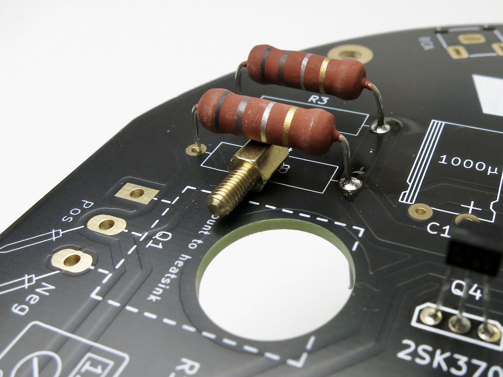
Large Resistors
| Board Reference | Part |
|---|---|
| R1 | |
| R2 | |
| R3 | |
| R4 |
Solder the large resistors.
The large resistors get warm during operation. Some space off the PCB will help airflow. You can use the brass standoff to gauge the space under the large resistors. It helps to solder one leg from this side before flipping the PCB over.
END_SECTION
Potentionmeter & Small Capacitors
| Board Reference | Part |
|---|---|
| P1 | |
| C3 | |
| C4 |
P1 is keyed and cannot be inserted backwards. Solder the C3 and C4 capacitors with the long leg in the + hole.
END_SECTION
Small Signal Transistors
| Board Reference | Part |
|---|---|
| Q3 | |
| Q4 |
Q3 is slightly bigger than Q4. Both Q3 and Q4 are directional. The outline of each transistor is drawn on the PCB - the slightly longer/bigger face of the transistor is called the ‘flat’ and you should align it with the longer side of the outline on the PCB.
END_SECTION
Large Capacitors
| Board Reference | Part |
|---|---|
| C1 | |
| C2 |
The leads of C1 & C2 need to be bent down prior to installation. Use a long screw as a bending guide to ensure the bend does not occur too close to the packaging. Before making the bend, note of the direction of the capacitor. The long leg should go in the + hole and the capacitors should lie on the PCB outlines.
END_SECTION
Power Switch
| Board Reference | Part |
|---|---|
| SW1 |
Make sure the switch is flat against the PCB before soldering. A round cap is provided to attach to the button.
END_SECTION
DC Power
| Board Reference | Part |
|---|---|
| J1 |
Make sure the DC Power Jack is flat against the PCB before soldering.
END_SECTION
RCA Jack
| Board Reference | Part |
|---|---|
| J2 |
Again, make sure the RCA Jack is flat against the PCB before soldering. It may take some effort to push the RCA Jack into the PCB.
END_SECTION
Speaker Posts
| Board Reference | Part |
|---|---|
| J3 | |
| J4 |
Solder the binding posts to the screw terminal before adding them to the PCB. This takes patience and heat - use a larger soldering tip if possible. Align the holes in the binding post to be vertical when installed. Some binding posts run out of threads when they’re screwed all the way in. Adding the included split washer between the parts will help the threads stay engaged and hold alignment while soldering. This will be easier if you remove the nut portion of the assembly, there will be less thermal mass to heat for effective soldering.
END_SECTION
LEDs
| Board Reference | Part |
|---|---|
| D1 | |
| D2 |
One side of the PCB is complete! Flip the PCB and insert the LEDs D1 & D2. Make sure the long leg goes in the + hole. If you dont like the color changing LEDS, you can subsitute for solid color LEDs of your choice, or leave them out entirely.
END_SECTION
Stand Offs
| Board Reference | Part |
|---|---|
| BSO1 | |
| BSO2 | |
| BSO3 | |
| BSO4 |
Screw the 4 brass standoffs into the outermost holes along the heatsink.
END_SECTION
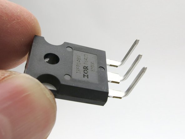
Transistor Preparation
| Board Reference | Part |
|---|---|
| Q1 | |
| Q2 |
The Q1 & Q2 transistor legs need to be bent up by 90 degrees towards the plastic side of the body, right at the point they narrow. Bending can be done with pliers but the leads will naturally bend at the correct point even when done by hand.
END_SECTION
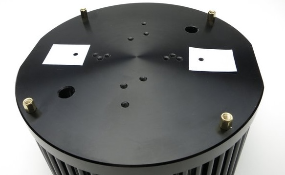
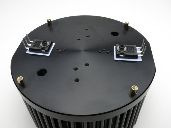
Insulating & Securing Transistors
| Board Reference | Part |
|---|---|
| Q1 | |
| Q2 |
Install the insulator pads to the head sink. Make sure they are clean and free of any metal crumbs or solder blobs.
Attach the Q1 & Q2 transistors to the heatsink with the screw and washer. It does not matter which side is Q1 or Q2. Do not tighten the screws yet - you will have to adjust the location of the transistors and screws in the next step.

END_SECTION
Aligning Transistors & Attaching PCB To Heatsink
| Board Reference | Part |
|---|---|
| Q1 | |
| Q2 | |
| NSO1 | |
| NSO2 | |
| NSO3 | |
| NSO4 |
Before adding the PCB to the heatsink, make sure:
- the brass standoffs are inserted and secure
- the large Q1 & Q2 transistors have the insulators aligned nice and square under them
- the large Q1 & Q2 transistors are not touhcing the metal of the heatsink
- the screw and washer holding the large Q1 & Q2 transistors are attached but not tightened
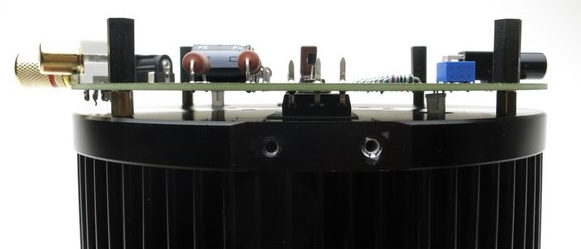
The PCB and the heat sink go together so the flat parts are aligned. Align the 3 legs on Q1 & Q2 with their holes in the PCB.
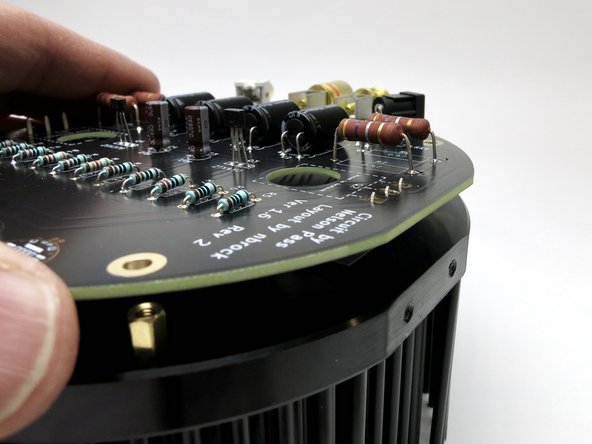
Gentle nudge the PCB to align the mounting holes over the brass standoffs and insert and attach the 4 black ‘legs’ into the brass standoffs.
With the PCB secured by all 4 screws, you can now tighten the Q1 & Q2 screws firmly. Do not over tighten.
Solder Q1 and Q2 to the PCB.
END_SECTION
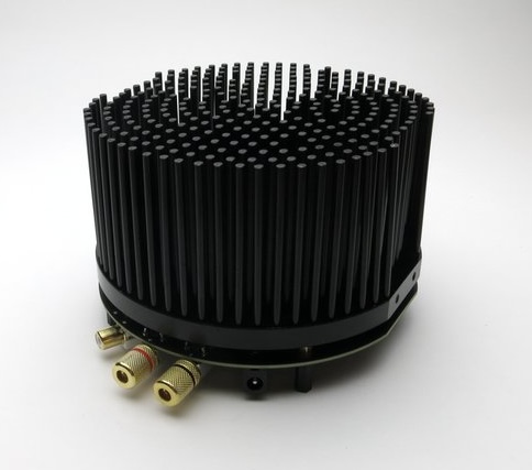
Take a moment
It looks like a mechanical hedgehog!
END_SECTION
Set the DC Balance to 12V
| Board Reference | Part |
|---|---|
| Q1 | |
| P1 |
For best results, allow the amp to warm up for about 30 minutes. Connect a DC volt meter to Q1 as indicated by the diagram on the PCB. Make small adjustments to the trim pot P1 as tiny adjustments will have a large impact on the voltage, and the initial change in response to your adjustment will ‘bounce’ before it settles. Aim for between 11.5V and 12.5V. Be patient. Go slow. Enjoy the process.
END_SECTION
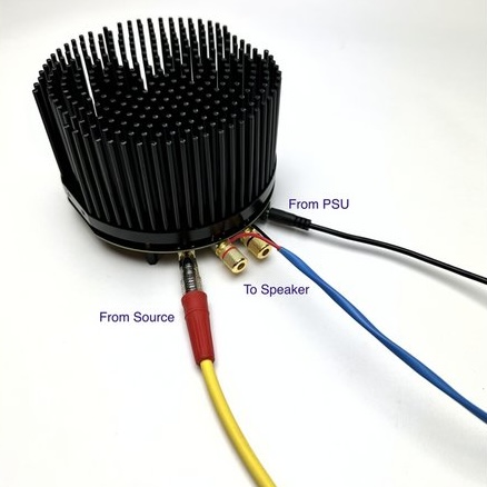
Connections & Inputs
| Connector | Board Reference | Cable |
|---|---|---|
| Black Barrel Jack | J1 | Power Supply |
| RCA Jack | J2 | Audio Input |
| Speaker Posts | J3 & J4 | Speaker Wires |
END_SECTION
Sign Your Work!
You did it! Congratulations. Remember to sign and date your new amplifier.
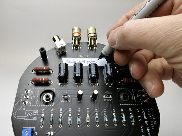
A big thank you to 6L6 for helping create this tutorial. You can view an alternate version over at diyaudio.com